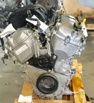
Here you can find information regarding the assembly of the Ford 3.7L DOHC engine. In this guide we will start from the inside of the engine including the crankshaft, connecting rods, and piston ring installation and then move outwards all the way to the pulley belt system. Along the way correct procedures and torque specs will be given to aid in the assembly of the engine. Feel free to start from the beggining and work your way outwards or skip ahead to your current position in the engine for what you may need.
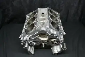
CRANKSHAFT MAIN CAPS INSTALLATION
The 3.5L engine block main bearing caps should be inspected for any defects or flaws before installation. Be sure to lubricate the bearing surfaces prior to installation. Once prepared you can place the caps onto the crankshaft and begin tightening the bolts down in a multi stage process. The first being 44 ft-lbs starting from the middle and going outwards. Then on the second pass you can go an additional 90 degrees in the same pattern as before. On this engine there is additional side bolts which aid in holding down the main bearing caps. These should be tightened down in a sequence starting from middle to the outside and torqued to 33 ft-lbs and then an additional 90 degree turn. Once finished make sure to turn the crank over to ensure there is no binding and that it rotates smoothly. After ensuring the crank turns smoothly we can install the main bearing cap support brace which is placed on top of the bearings and tightened down in sequence starting at 15 ft-lbs and then an additional 180 degree turn or half a turn.
Mustang 3.5L DOHC Main Cap Torque Specs : 44 ft-lbs + 90°
Mustang 3.5L DOHC Main Bearing Side Bolt Torque Specs : 33 ft-lbs + 90°
Mustang 3.5L DOHC Main Support Brace Torque Specs : 15 ft-lbs + 180°
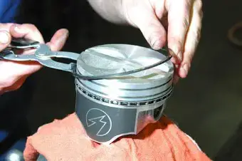
PISTON AND CONNECTING ROD INSTALLATION
To install the pistons and connecting rods you must first install the piston rings into each piston. Be careful not to stretch the rings or break them during installation. Make sure to put the correct rings in the correct positions, this can be determined by looking at the instructions given with the new rings. Each ring manufacturer is different so be sure to check for your specific rings. Once the rings have been installed you can now fit the connecting rod bearings into the end caps and lube them up with oil or lithium grease. The piston can now be lowered into the cylinder, make sure the dot or mark is facing the front of the engine and that you don't scratch the cylinder. Once installed you can match the connecting rod caps with the correct rods and start to torque the connecting rod bolts to 17 ft-lbs then 32 ft-lbs and finally a 90 degree turn for each bolt while doing them in series. After all are done rotate the crank to ensure all pistons move smoothly in and out of their cylinders and nothing binds.
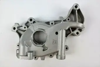
When installing the oil pump be sure to use the proper sealant around the pump base if neccessary to ensure that oil pressure doesn't drop due to leakage. After preparing the contact surfaces carefully install the oil pump onton the crankshaft by aligning the crankshaft end with the hole on the center of the pump. Once installed put the bolts in and torque them to 8 ft-lbs. The oil pump pickup tube can be installed onto the pump itself and torqued down to 8 ft-lbs. After torqueing the bolts be sure to prime the pump with the proper engine oil, this ensures that when the engine is initially started that oil is already present in the pump and that the engine doesn't start without any oil flowing inside of it.
The first thing you must do when installing cylinder heads is to ensure both the block and head surfaces are completely clean from dust, oil, and any debris. The next thing you must to is to set the camshafts to their correct positions to prevent any valves from hitting pistons during installation and torquing of the head bolts. Much the same you have to set the pistons to their correct locations, typically this means putting the #1 piston to TDC or Top Dead Center. Once everything is ready you can install the head gasket onto the engine block by aligning the alignment dowels. Something I usually do is spray down the head gasket with some engine copper spray from permatex which you can find here, this ensures that any gaps that could be present between the 2 surfaces gets filled with the spray. It also helps to transfer heat between the 2 metals. With the gasket in place you can set the cylinder head onto the gasket and block, if needed have someone assist with this process as the head can be heavy and you don't want to scratch anything or drop it! Once the head has been placed you will want to start installing the head bolts to make sure it doesn't move. Be sure to buy new head bolts as many manufacturers use TTY or Torque to Yield head bolts meaning they stretch during torqueing and cannot be used twice. Also make sure to lubricate the bolts in clean engine oil before installing them into the head. Once all the head bolts have been installed and finger tightened you can start the torqueing process, almost all head bolts have a multi-step process for torqueing. The 3.5L DOHC starts off with 30 ft-lbs and then requires you to back them off a full turn. Then you must again torque them to 26 ft-lbs and add 90 degrees and then an additional 90 degrees and finally a 45 degree turn by going through each bolt with each step. After torquing the heads are completely installed and you can now move to intalling the timing.
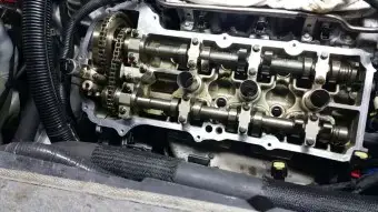
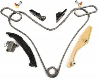
On the Ford 3.5L Duratec DOHC engine there is 2 camshafts per cylinder head and 2 timing chains which run the timing system on the engine. To install the timing system you can start by installing the proper camshaft into the correct cam journals. Each head has an intake and exhaust camshaft which will need to be oiled up and then placed into the journals on the cylinder head. Another thing to note is that ford marked each cam with LH or RH and exhaust or intake so you can tell where each goes. With the cams in place the camshaft journal caps can be tightened down to 8 ft-lbs. Once all the camshafts have been in place you can install the crankshaft timing sprockets onto the crankshaft. Moving to the upper end we will need to install the timing chain guides onto the engine block. The timing guides can be torqued down to 8 ft-lbs. Now before we start installing chains we need to install the secondary timing tensioners into each side of the engine and set them preloaded. To do this there is installation clips that can be pushed in and pulled out once the tensioners are in place. Push the tensioners into place and pull out the clips but don't mess with the tension portion. With the tensioners in place we can now install the camshaft VCT sprockets with their own timing chains onto the camshafts. Each series of sprockets has a timing chain which keeps them correctly timed with each other. Be sure that you keep the timing chain in place and on the correct gear teeth when installing. Once in place you can hand tighten the camshaft sprocket bolts. Once hand tightened and everything is in place you can torque the sprocket bolts to 30 ft-lbs, then loosen a full turn, tighten to 18 ft-lbs, and finally an additional 180 degrees. The secondary tensioners can now be actived and tension up the secondary timing chains. Now we can move to the main timing chain which connects to the 2 intake sprockets, the water pump, and the crankshaft sprocket. Before installing this chain we need to install the 2 long guides that range from the bottom of the engine to the top. These can be tightened to 8 ft-lbs. The primary tensioner can also be installed and torqued to 8 ft-lbs. The chain can now be installed within the guides and the tensioner released to tighten up the chain. The timing of the engine is now set and you can move onto the next phase.
Mustang Crankshaft Position Sensor Torque Spec: 8 ft-lbs
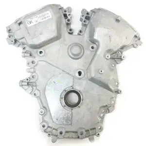
The timing cover on the 3.5L DOHC is used primarily to cover up the timing system and to keep oil from exiting the engine. For this reason I recommend the use of some silicon sealant as well as a new rubber gasket when installing the timing cover. Also be sure to clean both surfaces really well before placing the cover on. Once you can the gasket and silicon in place on the cover and both surfaces have been cleaned you can place the timing cover over the timing chains and start to bolt it into place by tightening all the bolts to 8 ft-lbs. From here we can start to tighten the outside permiter bolts to 15 ft-lbs and an additional 45 degree turn. The bolt in the middle of the cover can be tightened to 15 ft-lbs and then an additional 90 degree turn and the one located on the left side of the engine can be tightened an additional 45 degree turn.
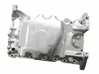
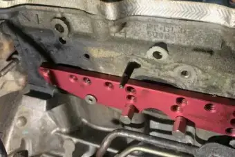
Much like the timing cover on the 3.5L DOHC the oil pan plays an important role in keeping the engine oil inside the engine. For this reason I recommend using a new gasket as well as some silicone sealant during installation. Using the same technique as before with the cover you clean the surfaces of both the oil pan and the engine block and then install the new gasket onto the block and then follow it up with some silicone sealant. Be sure to follow your sealants instructions to ensure you get the best seal from your application. The oil pan bolts torque to 15 ft-lbs and then an additional 45 degree turn in a cross pattern design. Along with the pan is the oil pan drain plug, this gets removed and reinstalled quite frequently and can be torqued down to 20 ft-lbs.
Mustang Oil Pan Torque Specs : 15 ft-lbs + 45°
Mustang Oil Drain Plug Torque Specs : 20 ft-lbs
VALVE COVERS INSTALLATION
The valve cover installation is rather simple, there are rubber seals for each bolt hole and a silicone gasket that prevents oil from leaking out of the engine. It is recommended to replace both the seals and the gaskets although if they are in good condition you can reuse them. If you do choose to reuse them I would use some silicone sealant along with the silicon gasket to ensure it does not leak. The valve cover bolts torque down to 177 in-lbs or about 15 ft-lbs and then an additional 180 degree turn in a criss cross order. Be sure not to miss any bolts to avoid having oil leak out onto the exhaust pipes and cause a lot of smoking.
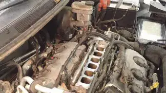
When installing the intake manifold you want to make sure you have all the surfaces as well as intake holes cleaned out before placing the manifold into position. Once cleaned you can then place the lower intake manifold gaskets into the lower intake. If you want you can also use a little bit of sealant on the gaskets to help ensure there are no leaks. With the gaskets in place you can now put the lower manifold down onto the heads and begin to install the bolts. The lower intake manifold bolts torque to 15 ft-lbs and then an additional 180 degree turn and can be tightened starting from the inside and going outwards. The next part of the intake is the upper intake manifold. You can prepare the gaskets for this part much the same as the lower intake but this time when you put it in place and start tightening the bolts torque them to 8 ft-lbs in a cross pattern. The COPs or the coils for the spark plugs get torqued down to 60 in-lbs or about 5 ft-lbs and the spark plugs themselves can be torqued down to 12 ft-lbs, be careful not to overtorque these as they can snap and cause big problems. When installing the fuel rail make sure that all the fuel injectors are in good condition and that all the o-rings are in place and are in good condition. If everything is good you can place the fuel rail into position and push the injectors into their holes and start to torque the rail bolts to 90 in-lbs or about 8 ft-lbs.
The exhaust manifold can be installed by cleaning the surface areas on both the head an the manifold itself and then by using the exhaust manifold gasket and putting it in place. Once the gasket is in location you can put the manifold onto the heads and begin to torque the nuts to 18 ft-lbs. I always use some copper spray from permatex on the exhaust manifold gaskets to ensure I do not end up with any exhaust leaks once done. When you go to install the engine into the vehicle or if it is already in the vehicle the torque specs for the exhaust manifold to the exhaust pipes or catalytic converter is 30 ft-lbs.
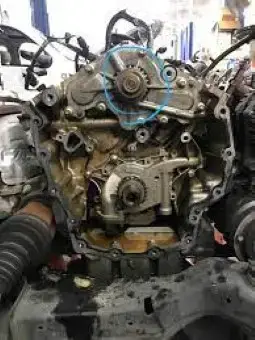
The water pump on the Ford 3.5L DOHC engine can be located either inside or outside of the front engine cover. Regardless of the version you have the water pump is ran using the timing chain and is located in the middle of the engine. The water pump should be tightened down to 8 ft-lbs and installed using a new gasket and clean surfaces.
Mustang Water Pump Torque Specs : 8 ft-lbs
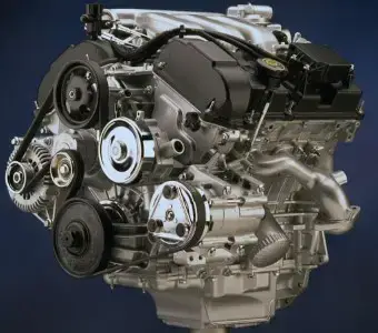
FRONT DRESS AND PULLEY BELT INSTALLATION
Most of what is left on the engine is just place and tighten objects such as the belt pulleys, belt tensioner, throttle body, crankshaft pulley, and motor mounts. If the items have a gasket and hold either oil or coolant inside the engine then feel free to add some sealant along with the gasket. Always be sure to inspect your gaskets and replace them if there is any deteriation or flaws with them. For the belt system the crank shaft pulley gets torqued to 37 ft-lbs and then an additional 90 degrees. The belt tensioner can be tightened to 8 ft-lbs and the idler pulley can be torqued down to 18 ft-lbs. When installing be sure they both turn smoothly and if they do not then replace them with new ones as the bearings can go bad. The engine motor mount can be installed onto the engine block if it hasn't been already, the torques for the mount to the block is 46 ft-lbs and then when installing the mount to the vehicle or frame it can be torqued to 66 ft-lbs. Finally the throttle body can be installed on top of the intake manifold with a good gasket and some added sealant using 7 ft-lbs in a criss cross pattern. For installing the belt you can use a tool to move the tensioner into its springed state and install the belt as shown in the picture.